Transformer Parts | A Complete Guide ?
Table of Contents
Introduction
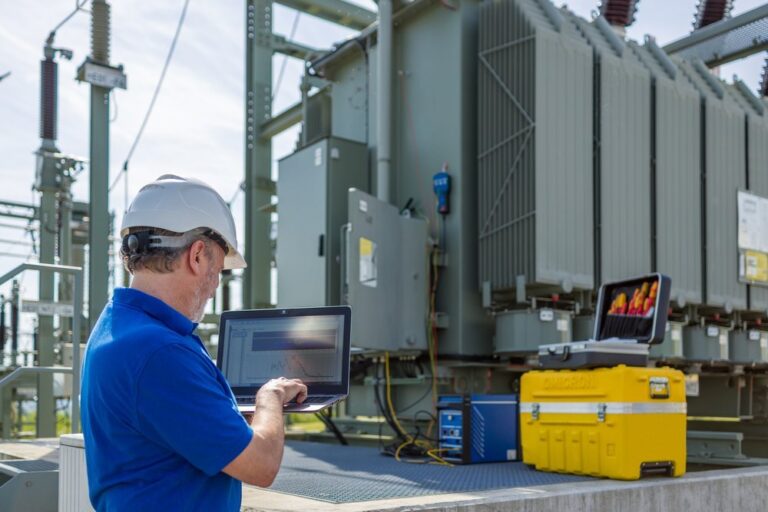
Transformers are very prominent electrical apparatus in the current electrical systems and networks. In one manner or another, they are always a present electrical apparatus when electrical energy is stepped up in voltage for electrical energy transmission and subsequently in voltage for home use. We never really worry about what happens in and on them, it just works! The transformer core and copper windings hold massively greater voltage and current in plain magnitude for long time, and the coils and cores command electricity to change voltage safely and effectively to allow power to be distributed as it is. Observing the basic parts of the transformer will help with everything from buying the transformer to doing your preventive maintenance and troubleshooting.
what is a Transformer
A transformer is a static electrical device that transfers electrical energy from one circuit to another circuit via magnetic flux and electromagnetic induction. It steps up (increases) voltage levels or, steps down (decreases) voltage levels, while transmitting the same power, minus losses, from the primary circuit’s side through to the secondary circuit’s side, to permit electrical power distribution to take place.
understanding the parts of a transformer ?
Whether you are an engineer, technician, maintenance personnel, or simply wishing to simply understand how transformers operate, knowledge around the parts of a transformer articulate advantages, including:
Improved troubleshooting
Better planning maintenance
Better sourcing of components that are of higher quality
Reduced losses gives downtimes; reduced operational costs
Improved energy efficiency; improved safety
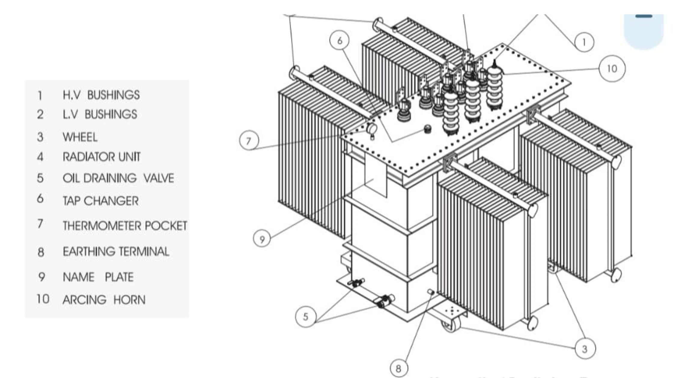
Parts of transformer
- Core
The core is the magnetic skeleton of a transformer. The core provides a low resistance path for the magnetic flux created from the alternating current that flows in the windings. The core is typically made of laminated silicon steel to reduce eddy current losses and improve energy used by the transformer. These laminations are electrically insulated from each other to reduce energy loss due to heat.
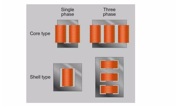
There are two main types of core configurations: shell type and core type. The shell type has the windings wrapped within the core, while the core type has the core wrapping around the windings. The design and construction of the core affect the performance, cost and weight of the transformer. A well-designed core will produce a highly efficient, low loss and compact transformer.
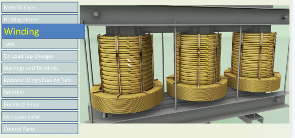
- Windings (Primary and Secondary)
Windings are important electrical components in a transformer and are responsible for transferring electrical energy from one coil to another by electromagnetic induction. The primary winding is connected to the input voltage source, where it creates a magnetic field. The secondary winding is comprised of the output voltage to the load. The transformer is designed to step up or step down the voltage level using the interaction of the primary and secondary windings.
Transformers can use copper or aluminum conductors for windings. Copper is more conductive and more efficient; aluminum is less expensive and lighter than copper. A winding configuration may vary, depending on voltage level and type of transformer. Common winding types are helical winding, disc winding, and cross-over winding. A properly designed winding will control resistance and avoid hot spots while maintaining reliability.
- Insulation
Insulation materials in a transformer are critical to avoiding electrical-short conditions and to protecting against failures since all conductive parts must remain isolated from each other. Insulating materials is especially important in transformers, which deal with high voltages, for safety and longevity reasons. Therefore, all insulating materials must hold up against thermal and electrical stresses over time.
Kraft paper, pressboard, and epoxy resin (especially in dry-type transformers) are some of the most common insulation materials. The insulation’s effectiveness is a key factor in the longevity of a transformer (in fact, most transformer failures can be traced back to insulation failures). Regular insulation testing and monitoring are essential aspects of preventive maintenance.
- Transformer Oil
Transformer oil has two primary functions: to supply electrical insulation and cooling of the internal components of the transformer. The transformer oil absorbs heat developed from windings and the core, then dissipates the heat from the transformer through the radiator or tank walls. The transformer oil also acts as an insulating lubricant between the energized components and the transformer tank.
There are two groups of transformer oils; mineral oils which are common because of their low cost and synthetic oils (silicone and esters) which are desirable because of their increased fire protection and environmental considerations. Regular oil sampling and testing can appreciably assist in determining when moisture has contaminated the transformer and acid and low dielectric strength has developed that may be detrimental to electrical performance.
- Conservator Tank
The conservator tank is a cylindrical, tank mounted above the main tank and is primarily used to accommodate the expansion of transformer oil with heat. When the transformer is operating, the oil expands and fills the conservator; when it cools and contracts, the oil moves back to the main tank.
The conservator tank is connected to the main tank by pipes and almost always has an oil level indicator to check the oil level. With the conservator in place, there should be no oil spilled onto the transformer and it helps the transformer maintain consistent levels of internal pressure, all of which help extend the life of the transformer and operate the transformer (with variable load and temperature) efficiently.
- Breather
The breather is a simple, but very important device that is fitted on to the conservator tank. The breather allows air to enter and leave the conservator as the level of oil changes, and its main purpose is to prevent moisture from entering the transformer. Moisture will reduce the dielectric strength of both the oil, and subsequently the insulation, even extremely small amounts of moisture in oil can severely limit its use in a transformer.
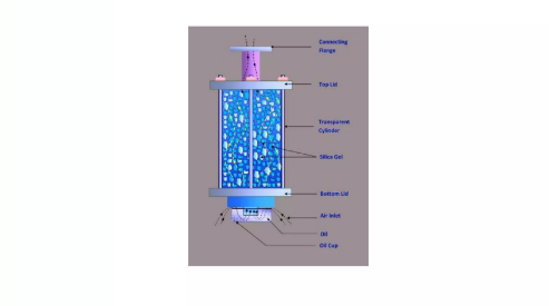
The breather contains silica gel that absorbs the moisture in the air entering the tank. The silica gel will turn pink when it is saturated and needs to be replaced or regenerated. If the breather is kept in good condition, the oil purity can be maintained, and oil moisture and insulation failures can be reduced, and the exposure of the transformer to moisture can increase its longevity.
- Buchholz Relay
The Buchholz relay is a gas actuated protection device used on oil-insulated transformers with conservator tanks. The Buchholz relay is used in the pipe that connects the main tank to the conservator. It acts as an indicator of gas buildup and oil movement due to an internal fault, i.e., arcing, insulation damage or overheating of the machine.
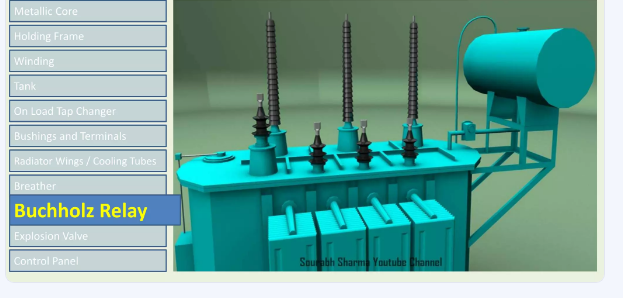
When a minor fault occurs, the gases that are produced will accumulate within the Buchholz relay, which triggers an alarm. If there has been a more serious fault, the relay can provide a trip signal to functionally disconnect the transformer. The Buchholz relay is an important early warning system to help prevent catastrophic failures and downtime.
- Tap Changer
The tap changer adjusts the transformer’s voltage ratio and keeps a constant appropriate voltage output even with changes in input voltage or load changes. The tap changer accomplishes this by switching the number of turns in the winding. Tap changers are particularly necessary in distribution and power transformers to maintain consistent voltages being applied over the permissible limits.
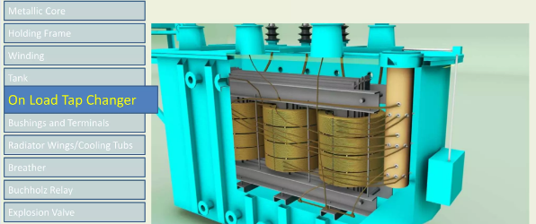
There are two forms; the off-load tap changer (OLTC), which is a tap changer that can only be manipulated with the transformer de-energized, and the on-load tap changer, which is a tap changer that enables changes in voltage while the transformer is under load. Tap changers are predominantly mounted on the high-voltage (HV) winding side of the transformer. Routine maintenance or servicing is required to avoid, for instance, contact wear or arcing problems.
- Radiators
Radiators are external metal fins or panels mounted to the transformer tank to help dissipate heat from the oil. As the oil gets hot, it rises inside the tank, goes through a radiator and then drops back down into the tank when cool, establishing a natural or forced convection loop in the process to keep the operating temperatures at appropriate levels.
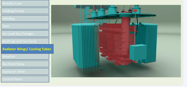
Radiators may be corrugated or finned, and may also have cooling fans to help with the dissipation of heat. Radiators are instrumental in preventing overheating, which can detrimentally affect insulation and shorten the life of the transformer. Radiator surfaces and location should be free from dirt or obstructions.
- Cooling Fans.
Cooling fans are utilized with radiators on larger or high-load transformers for temperature control purposes. A cooling fan moves air over the radiator surface to increase the rate that heat leaves the transformer oil and goes into the air around it.
Cooling types may be based on the use of forced and passive cooling (and use designations such as ONAN (Oil Natural Air Natural) or ONAF (Oil Natural Air Forced) depending on whether they are passive or fan-assisted cooling). Fans are typically temperature sensor controlled and automatically switch on at a prefered oil or winding temperature. While performing inspections we want to ensure that these fans will operate as necessary.
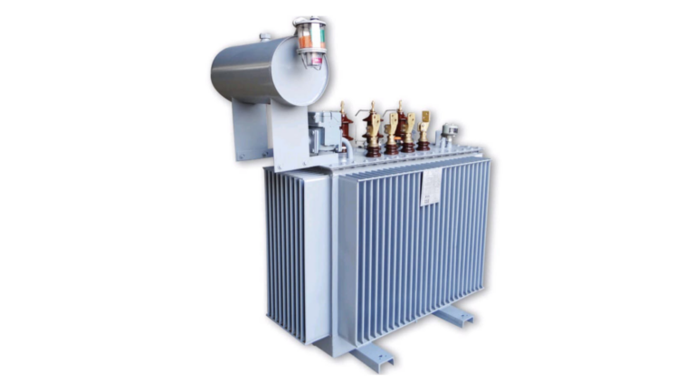
- Tank
The tank is essentially the outer shell of an oil-filled transformer containing the core, windings (coil), and insulating oil. In addition to assisting in the electrical operation of the transformer, the tank protects internal components from moisture, physical damage and other contaminants; the structure is made with mild steel and typically painted with anti-corrosive paint as a protective coating; the tank is a robust and sealed reservoir.
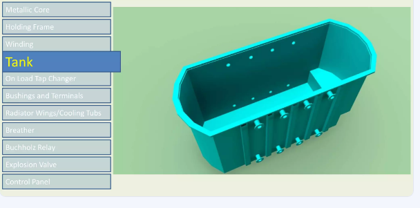
The tank is equipped with grounding terminals, temperature/pressure relief devices, thermometers, drain valves and other fittings. The tank has an important role in providing mechanical protection and heat dissipation. Any observable signs of leakage or corrosion should be tended toward prior to mechanical operating failure.
- Bushings
Bushings are insulated components that allow conductors to enter and exit the transformer. Bushings provide electrical insulation between the energized conductor and the tank wall, which is generally grounded; they make it possible to connect energized conductors to external power lines.
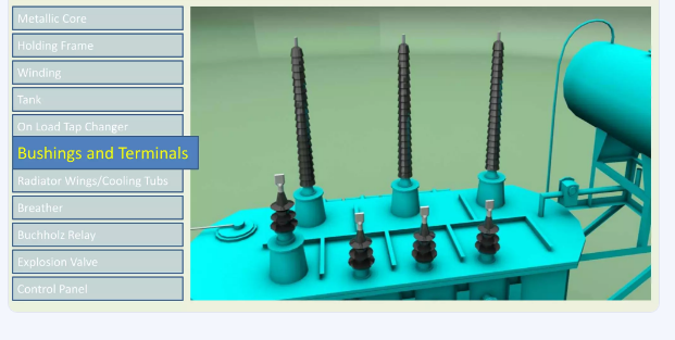
There are different types of bushings with the common types being oil-filled porcelain and solid porcelain. Each type of bushing is susceptible to contamination, tracking and mechanical stress; and as such, they require periodic visual inspection. Key points with respect to bushings would include the condition and observability of cracking; oil leakage; and surface discharge or tracking; and failure to attend to any of this prior to crater melt- down consistently causes flashover.
- Explosion Vent
The explosion vent is a safety device that relieves too much internal pressure during an event that leads to serious faults. It’s a pressure relief valve that prevents the transformer tank from rupturing due to a substantial amount of gas buildup or rapid oil expansion resulting from internal arcing or shorting events.
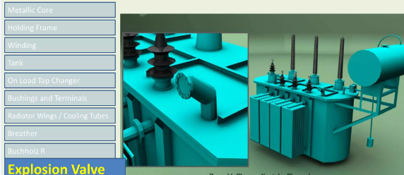
The explosion vent allows gases to slowly escape and minimizes the likelihood of upset, catastrophic failures, fire, or personal injury should an upset occur. The explosion vent can typically be found located on the top side of the transformer tank, and should be regularly inspected to be sure it does not have blockages or damage.
- Temperature Gauges
Although we generally don’t talk about temperature gauges or thermometers, temperature gauges are what indicates actual heat levels within a transformer. In particular, the readings regarding top oil temperature and winding temperature will be good indicators of transformer health within the operational envelope. Heat directly correlates to the breakdown of insulation; the hotter the transformer, the more likely the insulating material ages faster and leads to a greater chance of failure.
An array of modern designs exist (both analog gauges and digital gauges), and a number of manufacturers also offer models with alarms and/or fan controls built-in. Monitoring temperature live and documenting temperature trends serves several functions: managing the permanent load, making preventive maintenance decisions, etc. If any large or unexpected movements in temperature are encountered the situation should be explored immediately.
Maintenance Suggestions for Transformer Parts
A little maintenance will maintain reliability and longevity of transformer components. One of the most critical maintenance items is oil analysis, which tells you if you have issues with things like moisture contamination, acid formation, or a decreasing dielectric strength – each of which has a great impact on the insulating quality of the oil and less insulation can, without detection, can lead to internal failure. One of the simplest methods of maintenance consists of actual physical inspection. Performing a visual inspection a few times a week can be very useful in identifying any signs of oil leaks or physical defects such as cracks or damaged bushings – all of which should be properly investigated initially because they may be the early warning signs of development of greater problems.
For example, thermal scanning is a safe, non-invasive diagnostic technique to identify trends and the location of hot spots in windings, joints, or connections that sometimes can indicate looming overloading or components undergoing degradation. The breather should be observed regularly to ensure that the silica gel is still effective for moisture removal, a more saturate or discolored gel should be exchanged to discontinue moisture control of the inside of the transformer. The tap changer (on-load maybe) must be examined for contact wear, carbon build-up, and proper lubrication to ensure operational capability.
Diagnostics of Component Failures
Burning odor or discoloration
Sudden decrease in oil level
Trip or alarm activation
Significant changes in vibration or humming
Strides in temperature
Being able to recognize the signs early could minimize catastrophic damage altogether.
How to Obtain Quality Transformer Parts
Identify Recognized Manufacturers – ABB, Siemens, Schneider Electric and Eaton, among others
Verify certification – ISO, IEC, ANSI, UL, etc.
Verify specifications – component specifications should match the transformer design.
Request Test reports – Factory Acceptance tests, (FAT), insulation test, and others.
Establish warranty coverage – this is especially important for costly components like tap changers or bushings.
Conclusion
We often forget about transformer parts inside steel tanks that are insulated in oil, but they are the heartbeat of any electrical grid. Understanding transformer parts offers the potential to better design their utility, improve efficiency, increase operational safety and longevity to transformers. If you are installing a unit or working on maintenance, understanding these parts is beneficial.